Basic Steps of Flux Bend
STEP 1 - Import a CAD File
-
Import a Cad file using the Open menu.
-
Click the Open
 icon or go to File menu and select Open.
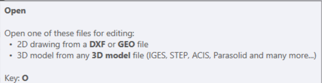
| Also, use the shortcut key O to import CAD files. |
-
Select the files you would like to import.
STEP 2 - Configure Materials / Thickness
-
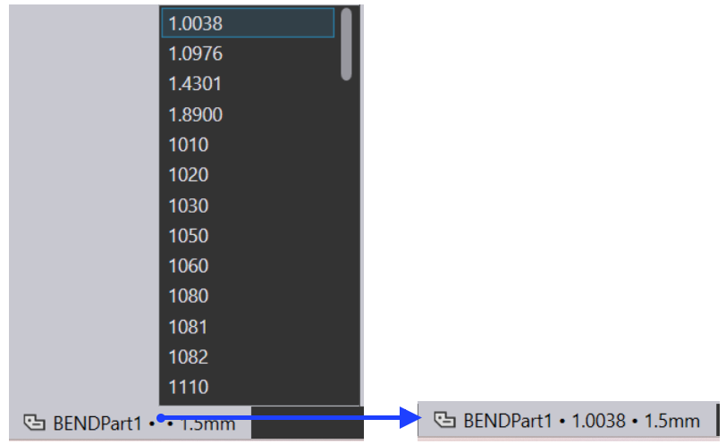
After importing a part, it may be necessary to set the material and thickness of the part.
-
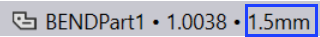
To set the material, click the material in the row of the open files at the bottom of the page.

-
Select desired material from the list.
-
Enter the desired Sheet thickness in 'mm'.
STEP 3 - Select Workflow
-
Depending on the type of CAD file imported and the program menu, additional menus and the functions are opened on the screen interface.
-
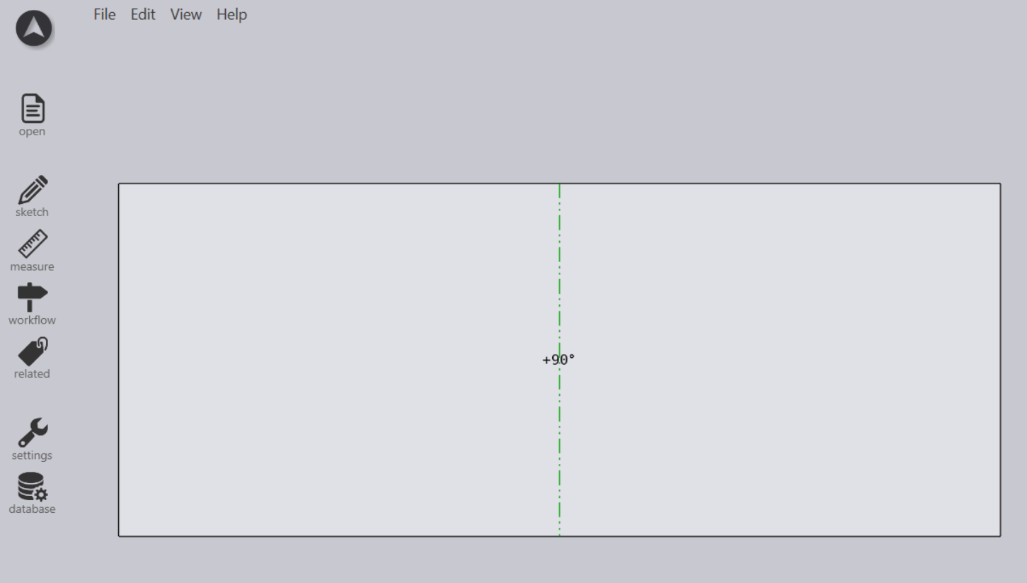
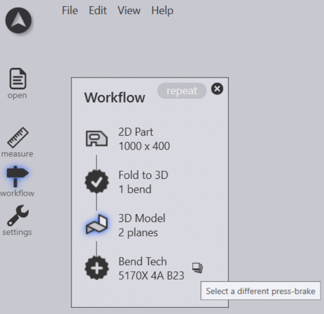
Upon opening the part, click on the workflow icon found on the left on the screen and Follow the Workflow menu step by step.
-
Click on the Workflow and it should open the Workflow panel as shown in the below screen
STEP 4 - Select Bend Machine
-
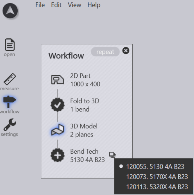
Use this option to shift between your desired machine to be used for bending a part.
STEP 5 - Add Bend Tooling
-
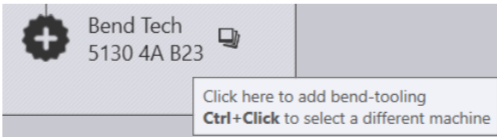
Click on the Bend Tech option to create the bend tooling automatically using the tools in the library.

STEP 6 - Edit Bend Tooling
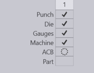
When you are in the bending view, the Bend Navigator panel appears along the top edge of the Flux window. This navigator provides a quick way to navigate through various bend operations, and also an instant view into various status-checks for every bend. It provides controls to view or stop the bending simulation. Here is an example of how the bend navigator looks:
Some basic settings for a bend can be viewed and edited by using the Bend panel.
-
To bring up the bend panel for a particular bend:
-
Click on a bend in the bend navigator
-
Click again on the same bend to open the bend panel to edit that bend.
-
An alternative method:
-
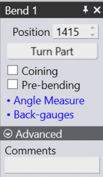
Ctrl+Click on a bend in the bend navigator, to select the bend and to open the editing panel for that bend. The Bend panel looks like the image alongside. This has some settings and operations for working on the bend.
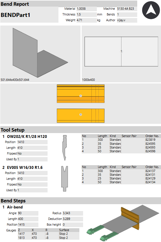
STEP 7 - Generate NC and Reports
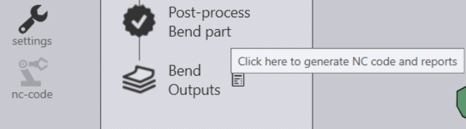
If there are no errors, you can click further on the Post-process bend part icon in the workflow to generate the outputs from bending. These are typically a bending report (containing a setup sheet) and the actual NC code for bending. By clicking on the icons near the bend outputs node, you can view these outputs. Once NC code has been generated, the NC code icon turns grey:
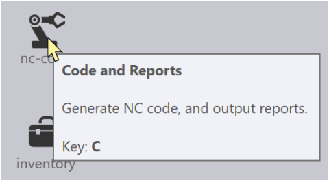
Also you can use the NC code icon to generate the Bend Outputs.
The path to the NC file is displayed at the left bottom corner of the screen.

To check the Bend Outputs, simply select the Bend Outputs option.